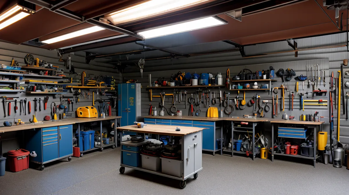
340 watts. That's what my Kill-A-Watt meter settled on the afternoon I ran my whole desk — monitor, dock, both hard drives — straight off power stored from the day before. For a minute, my off-grid garage setup felt like a finished project. Then a monsoon cell rolled over the Superstitions that same week, and it hit me that wattage was the wrong thing to be proud of. Bolting four 100-watt panels to the garage roof was the easy part. Grounding them — giving a surge somewhere safe to go — is what separates a real DIY safety setup from an expensive lightning rod, and it's the part I got wrong for longer than I'd like to admit.
Bolted to a Rack Isn't the Same as Grounded
Ask around at any maker space or solar forum and you'll hear the same assumption: if the panels are bolted to a metal rack, the system is grounded. That's the myth, and it cost me a chunk of a summer once I found out it was wrong. Equipment bonding and system grounding are two different jobs. Bonding means every metal part — panel frames, rails, enclosures — sits at the same electrical potential, so touching one part instead of another during a fault doesn't turn you into the path. Grounding means that whole bonded assembly ties into a rod in the earth, giving stray electricity somewhere to go besides you or your inverter. The National Electrical Code, specifically Article 250, treats those as two separate requirements, not one box you check by driving a rod and calling it done. Skip either half and you don't have a safe system — you have a well-organized hazard.
I'd already learned to distrust anything that sounded too simple. Years earlier I ordered a 'perpetual magnetic generator kit' off eBay, convinced by the listing photos, and got back a padded envelope of mismatched ferrite blocks with no generator anywhere in sight. Claimed output and measured output turned out to be two completely different numbers. Once you've checked one against the other and been burned, you stop taking a rack of bolted panels at its word.
My neighbor two doors down, Rosario Batista, is who actually made me check. Her husband is a licensed electrician, and he walks through my setup every so often just to keep me honest. The first time he saw the rack, he asked point-blank whether the frames and the mounting rails were bonded to each other — not just both vaguely 'grounded' in my head. I didn't have a real answer, which is usually a sign you don't actually know something.
Testing for Floating Voltage With a Cheap Multimeter
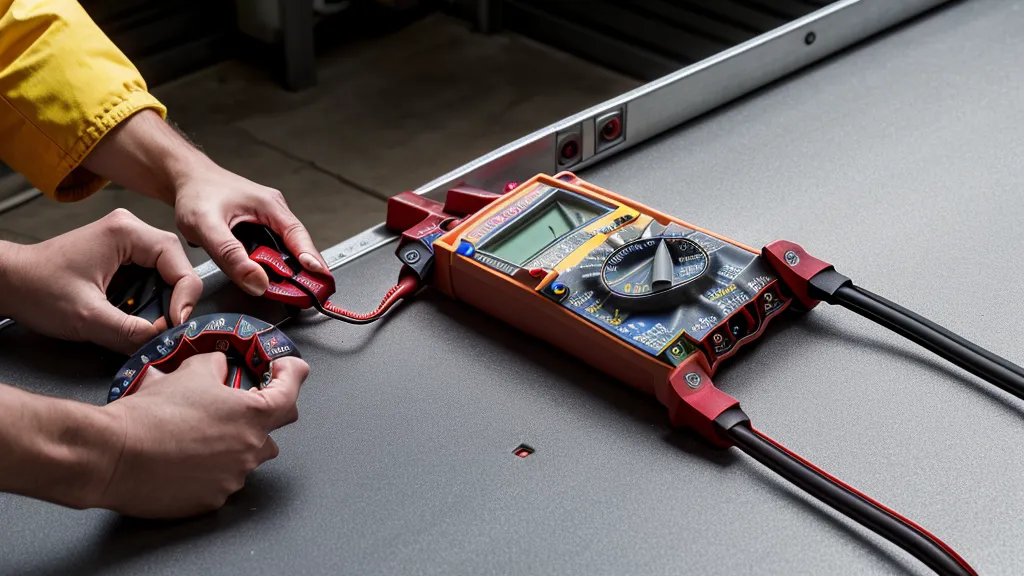
Grab a multimeter, set it to continuity, and touch one lead to a panel frame and the other to the mounting rail. A solid beep or a near-zero reading means the frame and rail are bonded. A wandering display means you've got what electricians call floating voltage — the metal parts sit at different potentials even though they look like one connected structure. That's exactly what I found the first time I actually tested my own rack instead of assuming it was fine.
The fix isn't complicated once you know it's needed: bonding jumpers between every frame and the rail, plus a lug tying the whole assembly into the ground wire. It's worth running this continuity check before touching anything else electrical in the system. I've covered how to test solar panel voltage with a multimeter at home in more detail elsewhere, and the same approach applies here, just aimed at the hardware instead of the output.
Buried Rods in Desert Soil
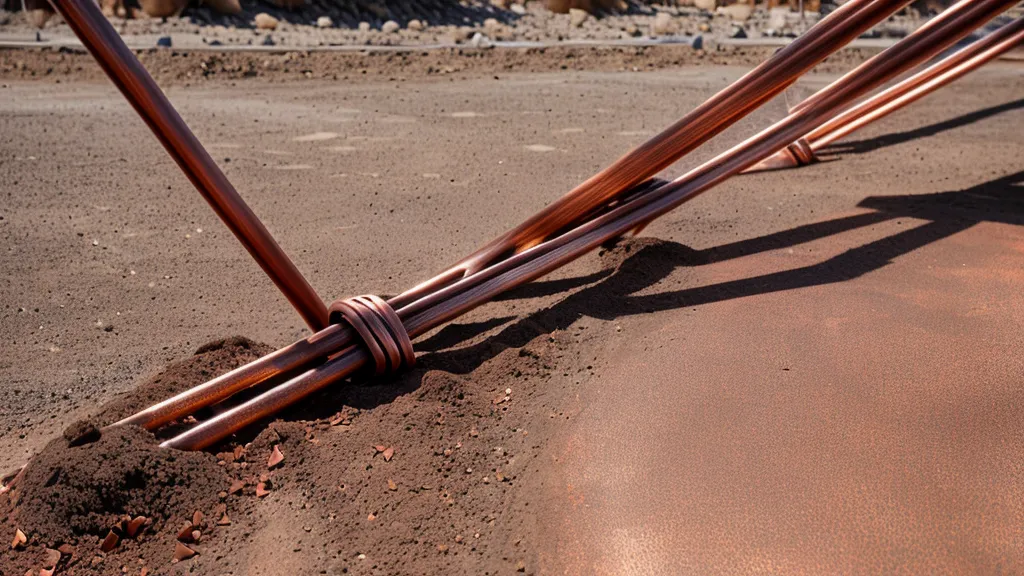
A second myth follows right behind the first: once a copper rod is in the ground, people assume the job's done. Code calls for an 8-foot copper-bonded steel rod, fully submerged, and in most of the country that's genuinely the whole story. Phoenix soil has other plans. What passes for dirt across most of Tempe and the surrounding suburbs is caliche — a hardpan layer with roughly the consistency of poured concrete — and driving a rod through it with a sledgehammer is miserable work by any measure.
By midday the driveway outside the garage door was shimmering with heat, and I was still three feet short of full depth. Every strike sent a flat metallic ring up through the sledgehammer and into my hands. Getting the rod fully buried turned out to be only step one, though. As the ground baked through late spring, my resistance readings started climbing instead of holding steady. Dry, rocky soil acts almost like an insulator — without moisture, there's nothing to carry a fault current away from the rod, and an 8-foot length of copper sitting in bone-dry dirt does roughly nothing during an actual surge.
Fixing that meant treating the rod as part of an ongoing system instead of a one-time install — keeping the surrounding soil slightly damp and using a conductive backfill around the electrode. In genuinely dry climates, some builders go further with a chemical grounding electrode: a hollow rod packed with electrolytic salts that slowly leach out to keep the soil conductive. A guy I know from the maker space in Mesa, Obinna Nwachukwu, ran into the exact same resistance problem with his shed array. He's the one who's always texting me part numbers from whatever electronics liquidator haul he found that week, but for a grounding rod and lugs, we both just bought fresh — not the kind of part worth gambling on.
Sizing the Ground Wire and Bonding It All Together
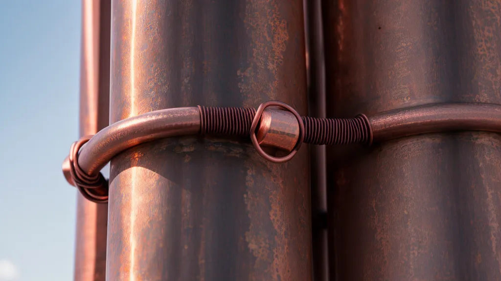
Once the rod holds a real ground, the wire connecting it to everything else needs to match the job. I ran 6 AWG bare copper, which is thick enough that it refuses to bend where you want it to and does not forgive a dull set of strippers. I spent an embarrassing stretch of one afternoon trying to strip it with a kitchen knife because my actual wire strippers had vanished somewhere into the pegboard chaos. Wire gauge matters just as much on the power side of the system — I went into that separately when I wrote about how to pick the right solar wire size for DIY projects. The short version: undersized wire anywhere in a solar setup, grounding included, just means more resistance than you want.
Connecting 6 AWG to an aluminum panel frame takes a UL-listed grounding lug, not just a wire wrapped around a bolt. You need something that actually pierces the anodized coating to get a real electrical connection underneath. The same bus that the rod feeds should also catch the inverter and the charge controller, so a fault inside either one has the same low-resistance escape route instead of turning the case into something you don't want to touch while checking battery levels. It's the same logic whether you're running a pure sine inverter or a cheaper modified sine unit — the bonding requirement doesn't change with the electronics.
What Actually Counts as a Grounded System
None of this makes a system bulletproof, and none of it substitutes for a real home energy audit if the actual goal is cutting the bill rather than just building something interesting in the garage. Grounding is also just one slice of a much bigger pile of decisions — PWM versus MPPT charge controllers, wiring panels in series versus parallel, how much battery bank you actually need, even a few degrees of panel tilt — and I've chased down most of those separately. If you ever tie a setup into the grid instead of keeping it island, backfeeding the main panel opens a whole separate transfer-switch conversation that belongs with a licensed electrician, not a weekend project.
What actually counts as grounded is boring, in the best way: every metal part bonded to the same potential, a rod that holds a real reading even when the soil is dry, and a wire path with nowhere for a fault to hide. It won't make anyone's electric bill drop overnight, and it won't impress anyone at a barbecue. But when a storm rolls over the mountains now and the panels are just sitting there catching sun, I'm not thinking about the $380 number that got this whole project started. I'm thinking about whether the ground path is doing its actual job, which, as far as my meter can tell, it finally is. It's the same instinct that keeps me reading pieces like how the Energy Revolution System helps reduce home energy use even after wrapping up a project — checking whether an idea holds up against what I've actually measured, not just what the packaging promises.